
For properties, a colon goes between the property name and its type. PlantUML’s terse syntax is generally formatted as a keyword identifier followed by the name of the subject. In between these markers is basic syntax that generates the diagrams, though diagrams can be as complex as is necessary All PlantUML files begin with the marker and end with the marker. Notice the PUML syntax and the corresponding visualization in the PlantUML tool window to the right of the editor window.
Uml diagram of uml editor code#
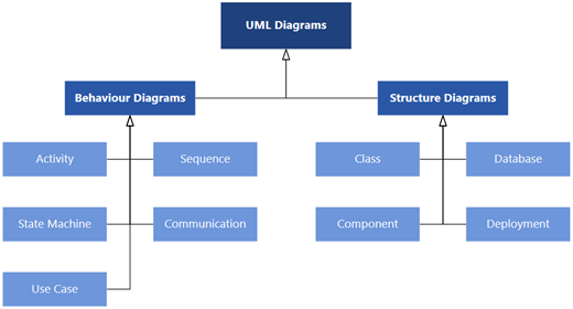
Because PUML syntax is clean, compact, and efficient, folks can use it not just for visual diagrams but also as a basis for code generation or documentation. Each new file that PlantUML creates contains example PUML, which is PlantUML’s own syntax for creating UML diagrams. Use the PlantUML plugin in Rider to create UML diagrams that can be integrated into your codebase. For example, a team that works on UIs might find Use Case diagrams helpful, while the back-end team might find Sequence and State-machine diagrams work better for their software. Instead, they tend to choose which UML diagram types are the most meaningful that help the team and other stakeholders better understand the software. Most teams don’t create every type of diagram for a system. In addition, PlantUML supports Object, Gantt, MindMap, Wireframe, and Work Breakdown Structure diagrams.
Uml diagram of uml editor software#

But it isn’t a programming language in the sense C#, Java, or Python are. We’ll create two of the most popular UML diagram types: Class and Use Case diagrams, to demonstrate what you can do with the PlantUML plugin in Rider. In this post, we’ll look at how PlantUML enables you to create various kinds of diagrams so that you can properly document your software. UML, or Unified Modeling Language, is, as the name implies, a modeling language that allows you to visualize systems.


 0 kommentar(er)
